a charged capacitor is connected to a resistor and a switch as in the figure below. the circuit has
Published 8 years ago • 36K plays • Length 3:38Download video MP4
Download video MP3
Similar videos
-
 4:10
4:10
physics webassign ch18 #12
-
 6:05
6:05
a 2.00-nf capacitor with an initial charge of
-
 7:31
7:31
the given pair of capacitors in the figure below is fully charged
-
 10:14
10:14
the circuit in the figure shows a capacitor, two ideal batteries
-
 7:07
7:07
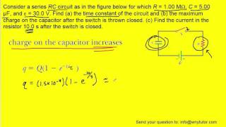
consider a series rc circuit as in the figure below for which r = 1.00 mω, c = 5.00 µf, and ε = 30.0
-
 6:00
6:00
testing capacitors for orientation of outside foil end
-
 9:08
9:08
capacitor substitution box! - the learning circuit
-
![how to spot a fault in a circuit, like a pro : hands on electronics [1]](https://i.ytimg.com/vi/ye9dguKy_Cs/mqdefault.jpg) 14:42
14:42
how to spot a fault in a circuit, like a pro : hands on electronics [1]
-
 6:15
6:15
a fully charged capacitor is connected to a resistor. when the switch is closed the capacitor will
-
 4:06
4:06
capacitors c1 and c2 are charged as a parallel combination
-
 4:21
4:21
in the figure, the capacitances are c1 = 1.0 µf and c2 = 3.0 µf, and both capacitors are charged to
-
 9:42
9:42
the figure below shows a 12.0 v battery and four uncharged capacitors of capacitances
-
 17:31
17:31
capacitor in a circuit with a switch
-
 8:43
8:43
in the figure the battery has a potential difference of v = 10.0 v
-
 5:39
5:39
switch s is closed at time t=0
-
 4:34
4:34
150-ch28 q6
-
 20:02
20:02
week 6 problem 12
-
 9:07
9:07
direct current circuits - physics -example - 3
-
 12:25
12:25
can the circuit shown be reduced to a single resistor
-
 7:29
7:29
rc resistor capacitor circuits charge discharge
-
 2:02
2:02
consider a series rc circuit for which r = 1.0 mω, c = 5.0 µf, and ε = 30 v as in the figure.
-
 6:49
6:49
consider the following parameters for the rc circuit in a defibrillator