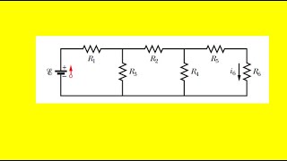
in the figure the ideal batteries have emfs
Published 3 years ago • 13K plays • Length 9:05Download video MP4
Download video MP3
Similar videos
-
 10:14
10:14
the circuit in the figure shows a capacitor, two ideal batteries
-
 9:57
9:57
in the figure the current in resistance 6 is i6
-
 8:43
8:43
in the figure the battery has a potential difference of v = 10.0 v
-
 6:24
6:24
in the figure what value must r have if the current in the circuit is to be
-
 8:20
8:20
two 1.50 v batteries with their positive
-
 13:06
13:06
the resistances in figure a and figure b are all
-
 11:12
11:12
using kirchhoff's rules find the current in each resistor shown in figure
-
 9:38
9:38
how to capacity test nimh rechargeable aa batteries
-
 6:22
6:22
how to make a rechargeable li-on battery 1.5 v aa size
-
 11:42
11:42
ebl lithium-ion aa & aaa batteries any good? find out!
-
 12:46
12:46
in fig. 27-55, the ideal batteries have emfs \( \mathscr{e}_{1}=200 \mathrm{~v} \) and \( \maths...
-
 5:57
5:57
a wire of resistance 5 ohm is connected to a battery whose emf
-
 13:50
13:50
video-19 ideal vs real batteries
-
 4:26
4:26
calculate the potential difference between points a and b in the figure
-
 5:06
5:06
thermal energy is to be generated in a 0.10 ω resistor at the rate of 10 w
-
 10:07
10:07
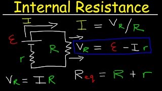
internal resistance of a battery, emf, cell terminal voltage, physics problems
-
 4:05
4:05
in the figure circuit section ab absorbs energy
-
 6:52
6:52
in fig. 27-63, \( r_{1}=100 \omega \), \( r_{2}=50 \omega \), and the ideal batteries have emfs ...
-
 6:11
6:11
the figure shows the circuit of a flashing lamp
-
 6:53
6:53
below is a circuit with four branches. the currents i1 and i2, and the emf ε1 are unknown. the curre
-
 5:30
5:30
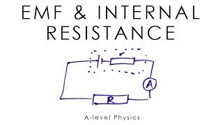
emf & internal resistance - a-level physics