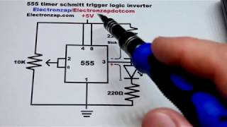
oscilloscope measurements of 555 timer schmitt trigger digital inverter circuit
Published 4 years ago • 1.3K plays • Length 4:38Download video MP4
Download video MP3
Similar videos
-
 11:20
11:20
555 timer schmitt trigger logic inverter circuit step by step build electronics by electronzap
-
 7:01
7:01
555 timer schmitt trigger logic inverter circuit
-
 9:32
9:32
how to wire 555 timer into a schmitt trigger digital inverter electronics circuits diy tutorial
-
 2:12
2:12
basic schmitt trigger digital inverter using 555 timer circuit learning electronics shorts 12
-
 1:24
1:24
ne 555 schmitt trigger inverter voltages oscilloscope measured
-
 6:24
6:24
quick 555 timer based schmitt trigger inverting logic switch circuit schematic diagram to breadboard
-
 3:21
3:21
how to wire up 555 timer as a schmitt trigger inverter circuit with trimpot for learning electronics
-
 31:07
31:07
how to use a digital oscilloscope...to test your tube amp! at the bench!
-
 11:51
11:51
how to measure ripple voltage on a switch-mode supply - workbench wednesdays
-
 4:19
4:19
555 pwm. simple circuits.
-
 2:37
2:37
electronics tutorial: 555 as schmitt trigger
-
 1:21
1:21
learn how a schmitt trigger works
-
 14:25
14:25
trimmer potentiometer trimpot voltage divider 555 schmitt trigger leds circuit oscilloscope measured
-
 6:32
6:32
555 timer schmitt trigger inverter demonstration circuit
-
 10:03
10:03
voltage of 555 timer output comparing ne555 to the cmos lmc555 as digital inverter schmitt trigger
-
 12:17
12:17
555 timer schmitt trigger inverter with leds trimpot controlled learning electronics lesson 0007
-
 4:08
4:08
how to make non inverting schmitt trigger with two 555 timers by electronzap diy electronics
-
 10:48
10:48
555 timer light level switch with schmitt trigger hysteresis demonstration bonus video
-
 1:43
1:43
schmitt trigger digital inverter using 555 timer set with trimpot voltage divider
-
 7:44
7:44
measuring a 555 on an oscilloscope - workbench wednesdays
-
 2:22
2:22
schmitt trigger
-
 7:31
7:31
solar powered kindle - part 13: schmitt trigger using 555 timer