ptc creo 7: how to assign a tolerance from the iso system of limits & fits to a shaft diameter
Published 3 years ago • 3K plays • Length 1:55Download video MP4
Download video MP3
Similar videos
-
 2:05
2:05
ptc creo 6: iso system of limits and fits
-
 7:27
7:27
tolerances & fits in ptc creo
-
 3:00
3:00
how to use pro/cmm to verify a geometric tolerance of cylindricity in creo parametric
-
 3:00
3:00
creating geometric tolerances using creo parametric
-
 5:45
5:45
ptc creo 7: assembly mechanism - impose limits on the movement
-
 43:16
43:16
ptc's tips & tricks for creo 7.0 (liveworx 2020 session)
-
 23:53
23:53
gia ptc creo tax (tolerance analysis)
-
 10:45
10:45
creo ptc-7 - how to install creo ptc 7 in easy way - cadd software
-
 1:15
1:15
support for tolerance table for iso models
-
 1:57
1:57
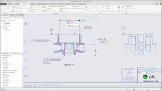
ptc creo 10: how to create a position tolerance in a drawing
-
 0:57
0:57
new to creo 4.0 - iso gps indicators in geometric tolerances (gtols)
-
 13:51
13:51
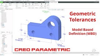
creo parametric - geometric tolerances (gd&t) - model based definition (mbd)
-
 6:34
6:34
creo tolerance analysis - tolerances – embedded gd&t pmi and 3dcs tolerances
-
 5:33
5:33
introduction to geometric dimensioning & tolerancing
-
 6:08
6:08
ptc creo pmi part 7 - how to push your gd&t and pmi changes back to creo
-
 9:29
9:29
understanding autogem limits and settings | creo simulate
-
 3:10
3:10
how to enable tolerance in creo | enable tolerance in creo drawing
-
 33:01
33:01
creating & editing geometric tolerances
-
 18:49
18:49
creo parametric - configuring the notification center
-
 2:54
2:54
ptc creo 7: drawings - how to create a centreline to indicate parts are aligned
-
 1:30
1:30
new to creo 4.0 - creating & editing geometric tolerances (gtols)
-
 5:51
5:51
ez tolerance analysis for ptc creo 7