rc low pass filter circuit lab experiment ac lab| circuit diagram | breadboard wiring
Published 3 years ago • 34K plays • Length 6:29Download video MP4
Download video MP3
Similar videos
-
 6:54
6:54
band pass filter | bpf| experiment ac lab| circuit diagram | breadboard| diploma btech
-
 5:17
5:17
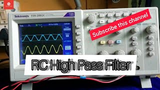
rc high pass filter circuit | circuit diagram i breadboard wiring| practical lab experiment
-
 2:52
2:52
rc low pass filter on breadboard and oscilloscope #lowpassfilter
-
 6:35
6:35
rc integrator circuit | circuit diagram| breadboard wiring | dso | practical lab experiment
-
 8:33
8:33
passive rc low pass filter tutorial!
-
 1:31
1:31
rc integrator
-
 1:49
1:49
rc low-pass step response - circuit simulator (circuitlab)
-
 5:23
5:23
rc differentiator circuit | circuit diagram | breadboard wiring | dso
-
![bode plot [frequency response] of rc low-pass filter - circuit simulator (circuitlab)](https://i.ytimg.com/vi/pJvwpVcQd38/mqdefault.jpg) 1:39
1:39
bode plot [frequency response] of rc low-pass filter - circuit simulator (circuitlab)
-
 14:59
14:59
to construct a rc low pass filter and draw its frequency response curve.
-
 1:54
1:54
rc low-pass filter (time-domain and frequency-domain explained)
-
 7:36
7:36
lpf working explained | malayalam| low pass filter| theory
-
 2:19
2:19
rc differentiator
-
 0:30
0:30
speaker bass and pass filter#shorts
-
 45:40
45:40
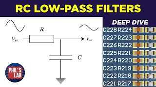
rc low-pass filter deep-dive - phil's lab #118
-
 4:34
4:34
low pass filter using op amp
-
 5:40
5:40
what is a low pass filter?
-
 17:29
17:29
electronics lab rc-circuits low – high pass filtering