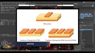
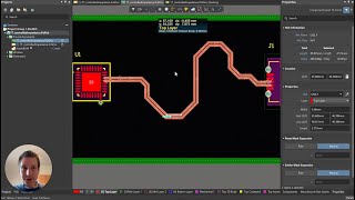
rf design in the pcb: transmission lines (coplanar)
Published 1 year ago • 11K plays • Length 2:40Download video MP4
Download video MP3
Similar videos
-
 4:59
4:59
rf design in the pcb: routing any angle or arc in altium designer
-
 3:01
3:01
rf design in the pcb: edge plating
-
 17:01
17:01
coplanar line with no ground plane | pcb routing
-
 10:11
10:11
how to draw microstrip and coplanar waveguide (cpwg) in altium designer
-
 12:17
12:17
altium designer rf impedance matching (e.g. 50ω, usb, ...)
-
 41:18
41:18
(2) rf and microwave pcb design - transmission lines and impedance - altium academy
-
 1:22
1:22
rf design in the pcb: plane connect - direct
-
 31:32
31:32
transmission line impedance calculation in altium designer - altium academy
-
 10:40
10:40
6 horribly common pcb design mistakes
-
 15:57
15:57
rf power amplifier design
-
 17:15
17:15
rf power amplifier design followup: pcb design
-
 6:43
6:43
how to auto-calculate impedance on single-ended transmission lines
-
 3:36
3:36
new coplanar transmission line structures for pcb design
-
 2:51
2:51
rf design in the pcb: rf materials
-
 11:08
11:08
primer on rf design | week 2.23 - planar transmission lines coplanar waveguide | purdue university
-
 31:44
31:44
rf and microwave pcb design - part 4: power dividers.
-
 17:36
17:36
starting an rf pcb design
-
 3:15
3:15
rf design in the pcb: distributed-element circuits
-
 21:05
21:05
(1) - rf and microwave pcb design - altium academy