the electrical circuit shown in fig 2 consists of resistors and voltage sources determine the curr
Published 2 weeks ago • 2 plays • Length 5:09Download video MP4
Download video MP3
Similar videos
-
 10:14
10:14
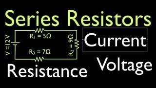
resistors is electric circuits (2 of 16) voltage, resistance & current for series circuits
-
 8:28
8:28
kirchhoff’s laws : in the circuit shown in fig determine vx and the power absorbed by the 12 ω resi
-
 13:56
13:56
determine the current in each branch of the circuit shown in figure.
-
 7:35
7:35
voltage and polarity in a series circuit
-
 12:25
12:25
can the circuit shown be reduced to a single resistor
-
 11:28
11:28
in the circuit of the figure below determine the current
-
 10:52
10:52
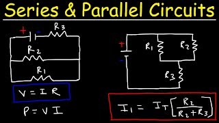
resistors in series and parallel circuits - keeping it simple!
-
 18:20
18:20
transistors explained - how transistors work
-
 16:22
16:22
sub panels explained - why are neutral and ground separated?
-
 10:39
10:39
parallel circuit - find missing voltage
-
 1:44:10
estc - week 6 s - 2/week7 s - 1
-
 30:32
30:32
series and parallel circuits
-
 11:59
11:59
(a) the current in the 20.0- resistor and (b) the potential difference between points a and b.
-
 10:28
10:28
consider the circuit shown in the figure below
-
 4:56
4:56
series and parallel circuits | electricity | physics | fuseschool
-
 13:36
13:36
dc electric circuits | superposition principle - two voltage sources | calculations & simulations
-
 14:06
14:06
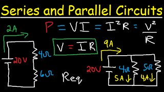
how to solve any series and parallel circuit problem
-
 12:51
12:51
resistors in electric circuits (4 of 16) adding resistors to series circuits, part 1
-
 6:59
6:59
circuit shown contains two batteries, each with an emf and an internal resistance, and two resistors
-
 9:02
9:02
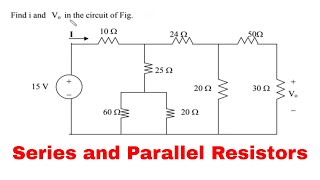
series and parallel resistors : find i and vo in the circuit of fig
-
 4:22
4:22
dc electrical circuit analysis: series-parallel circuits, part 2
-
 2:27
2:27
2 dc voltage source series-parallel resistor circuit find currents & voltages (problem & solution)